15W Single-Ended Tube Amplifier
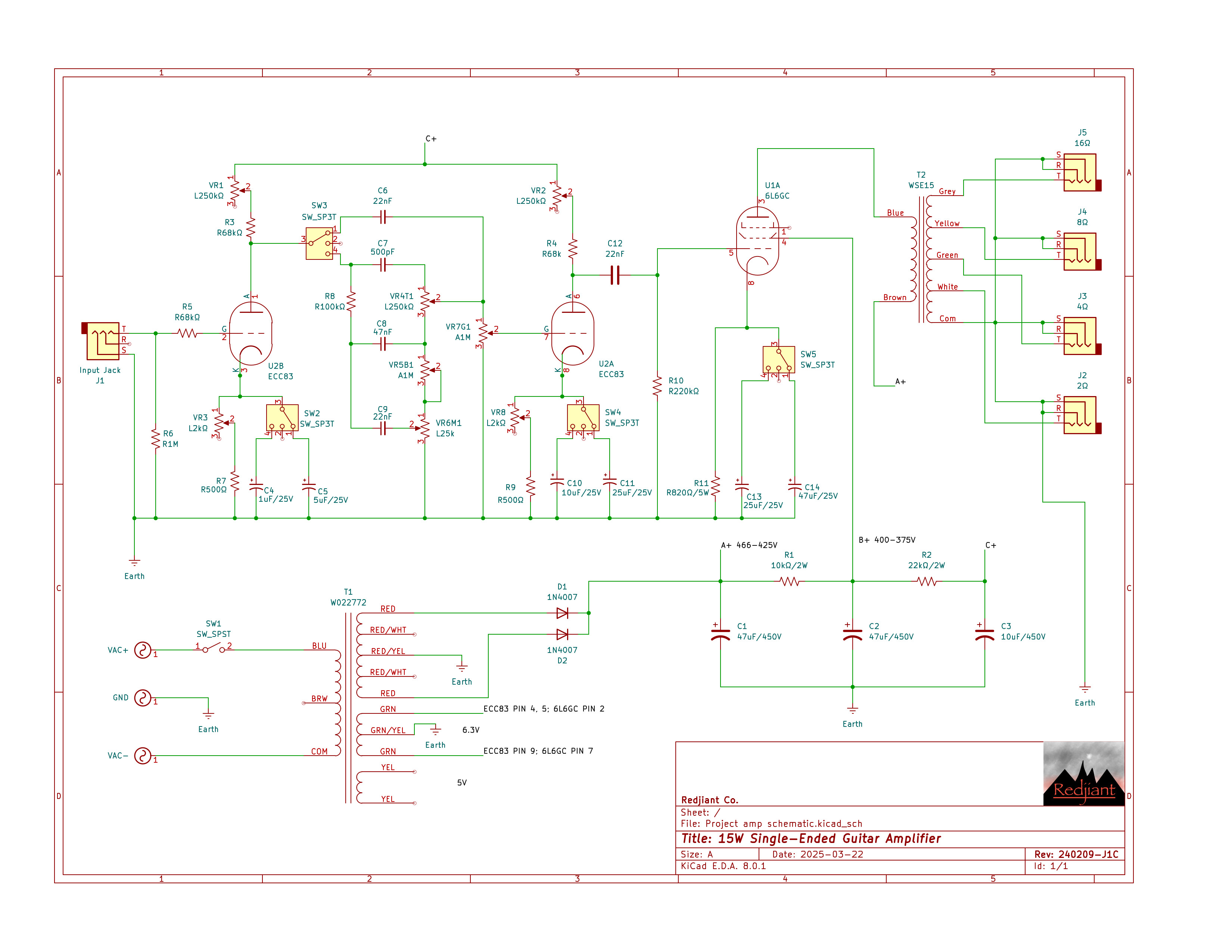
A 15 Watt Class-A guitar amplifier built around a 6L6GC output tube and ECC83 preamp tube. The amplifier was designed and built from scratch using available materials and components. Designed to allow the user to adjust circuit parameters and explore the full range of tube operation from clean and warm with plenty of headroom to current-starved high gain. Features a variable circuit with fixed offset values for the plate resistor and grid resistor on the ECC83 gain stages. Each gain stage has two switchable bypass capacitors to control gain and tighten low-end response. There is a bypassable tone stack, allowing the user to shape the response of the amplifier or bypass the tone stack to drive each gain stage without tone stack losses. The output transformer has 2, 4, 8, and 16 ohm secondary windings wired to output jacks to match the 6l6GC output to a range of speaker impedances. The components are housed in a custom-fabricated aluminum enclosure that was modeled and toolpathed in Solidworks for machining on a Tormach 4-axis mill.
This project started when I was working at James Loudspeaker, and I came back to it when I was enrolled in Physics II at Western Nevada College. I had the wild hair to build a tube amplifier using my circuits and soldering skills for prototyping crossover filters in the "E-lab" at JLS. I ordered the components and built an amplifier, but the result was a rather noisy and weak amplifier. I troubleshot the amplifier and found that my ground path was convoluted and the wiring was messy: I was looking at a complete redesign. I reached the limits of my knowledge with circuit calculations and datasheets, as well as spending a decent amount on the project. I had to buy a new vehicle at some point in this, and that put a damper on my progress. Fast forward to my time at Western Nevada College, and I revisited the amplifier with a fresh perspective and used it as my physics laboratory final project to analyze basic circuit fundamentals and physics phenomena such as thermionic emission. I designed a simple amplifier similar to a stripped down fender tweed champ to ensure I would have great success with my design. It had an input jack, volume, and output jack: a one-trick pony. I spent a few weeks designing the amplifier and calculating node current and voltage in the power supply and at the tubes. I built it in 14 hours across 2 days. It had a small short in the power supply, which caused the fuse to blow on power-up. I located the short in the power supply, and it powered up, sounding loud and full.
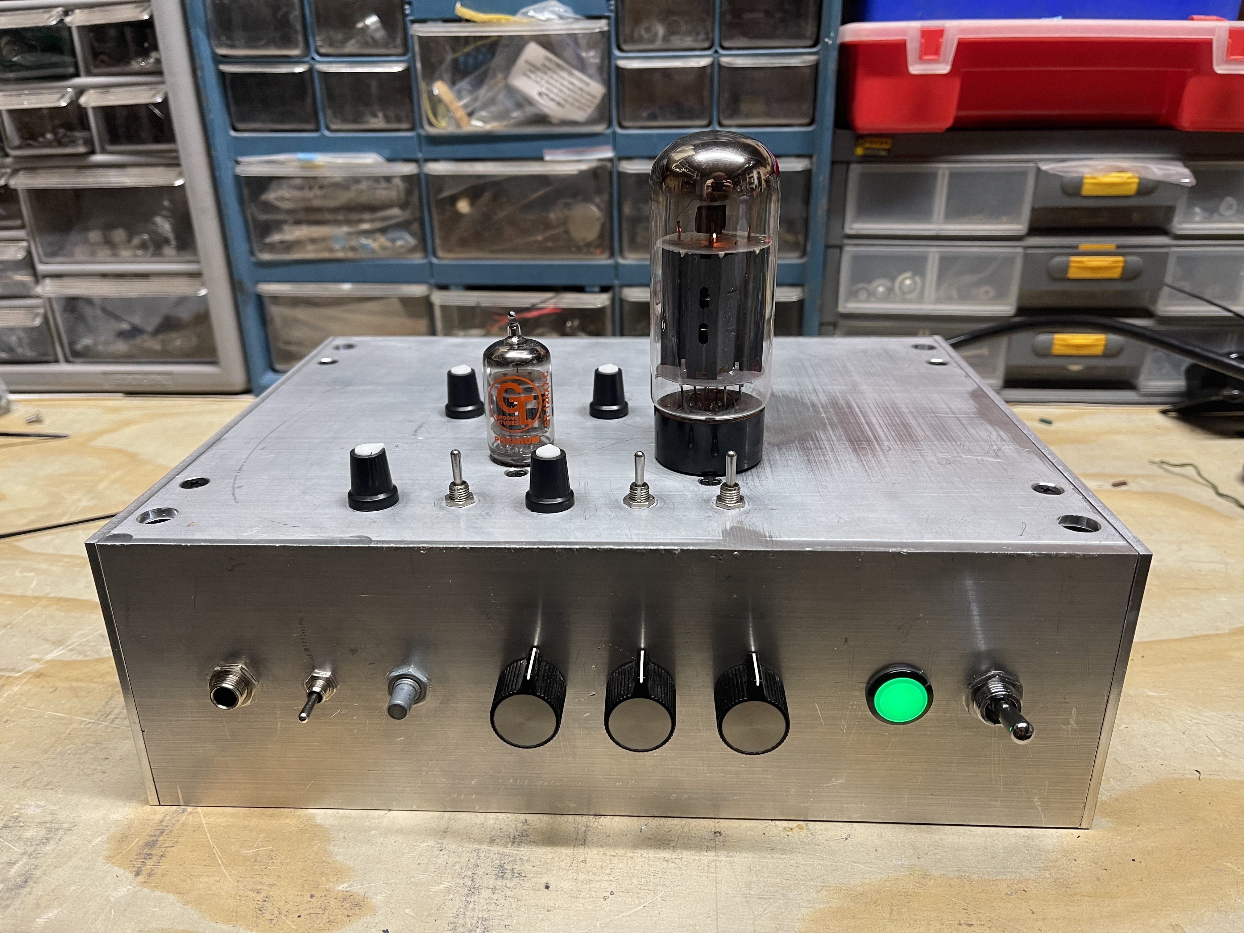
I needed an enclosure to house this amplifier because this prototype was dangerous. I had every component mounted to a flat aluminum plate and built the circuit on a solderable breadboard with the "traces" exposed so the signal path could be probed with an oscilloscope. It was convenient for prototyping, but it created significant exposure to the high voltage present at the plate and a direct path to ground through the prototype plate. I had the prototype collecting dust in the workshop because powering it up was cumbersome, and operating it was dangerous. I wanted to take this project to the next step as a functional amplifier. I had a few scrap cuts of an aluminum extrusion with endcaps to make a housing. I knew I had all the pieces for the amplifier, but machining the enclosure was difficult because I did not have access to a machine shop, or so I thought.
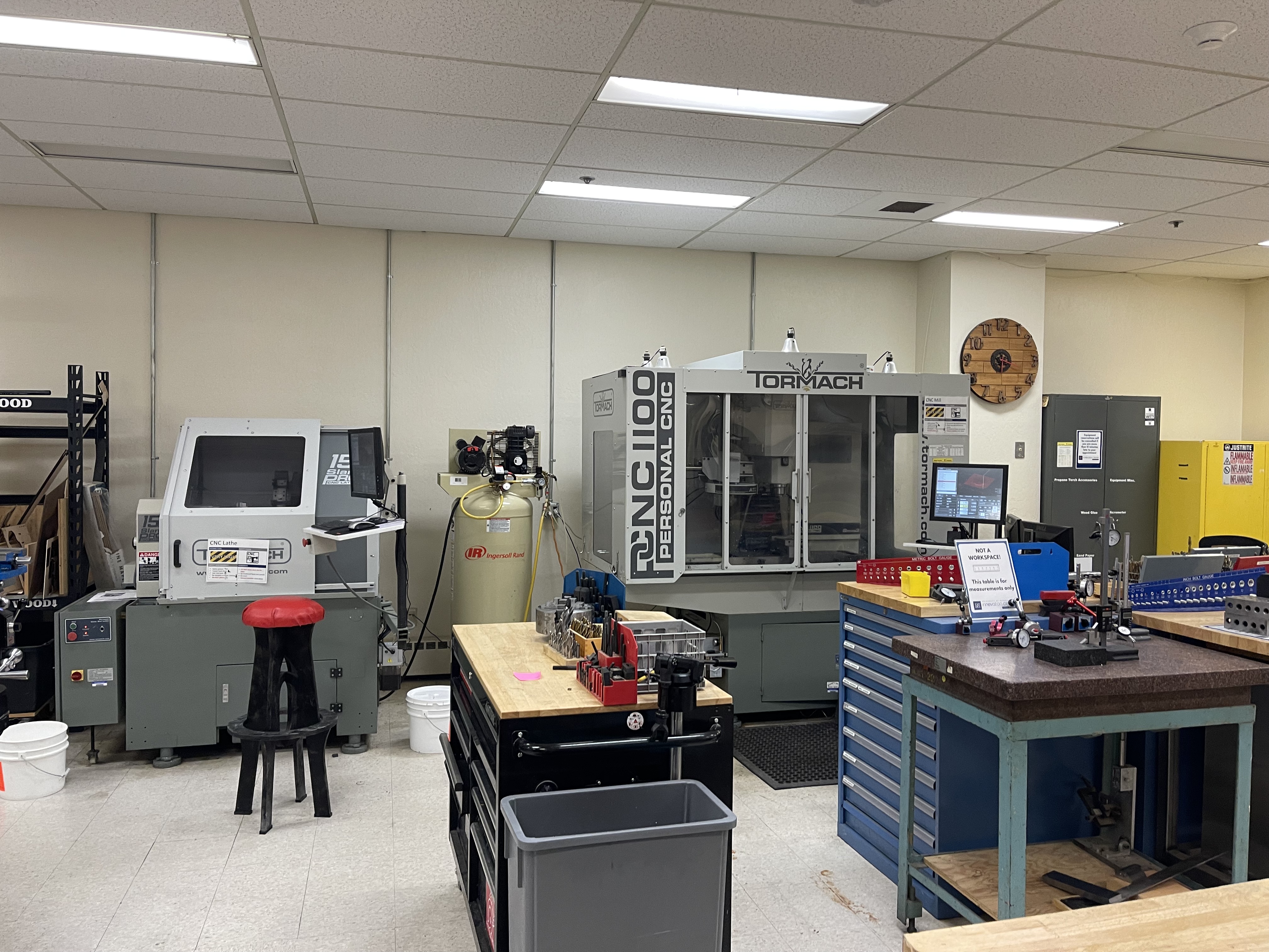
The makerspace at the Innevation Center is an underutilized resource at UNR. It's located off campus and in the basement of the building. There is a makerspace on campus, so it is frequently confused with the latter. When I toured the facility, I was excited to use the full metal and wood shop to gain experience with machinery I haven't had the opportunity to use. I had to go through general safety training, train on power tools and hand tools, and train on manual milling before I could start on the training for the CNC mill. I worked on training in the netal shop at the Innevation Center while I designed the amplifier and worked on a 15-credit courseload.
I needed to finalize the design of my circuit before I could finish the model of the amplifier enclosure in SolidWorks, let alone begin teaching myself to toolpath and export G-code. I started with the data sheets for the tubes and the transformers. I had a matching output transformer for the plate impedance of the output tube. My input transformer had plenty of current available for the single-ended amplifier, about 100mA, from the main secondary winding. I planned to make every component that I could adjustable so I could use the prototype to gain an intuitive sense of how changing each component affected the overall sound. I needed to estimate the range of current across
Notes for continuing: need a photo of machining the enclosure. Maybe look into posting videos. for story: designing the circuit. designing the housing and mounting locations, modeling all the components to ensure fitment, training in the innevation center, toolpathing in SWCAM, running the enclosure on the mill, troubleshooting the G code. final machining, building the circuit, building/testing the amp, conlusing paragraph
Technical notes / TLDR;
- Single-ended Class-A operation
- 15 Watts of power output
- Custom operating point selection via variable plate and cathode resistors for ECC83 gain stages
- Switchable bypass capacitors on all gain stages for a controlling gain and low-end response
- Tone stack to shape frequency response, which can be bypassed to allow the gain stages to feed directly into the next stage
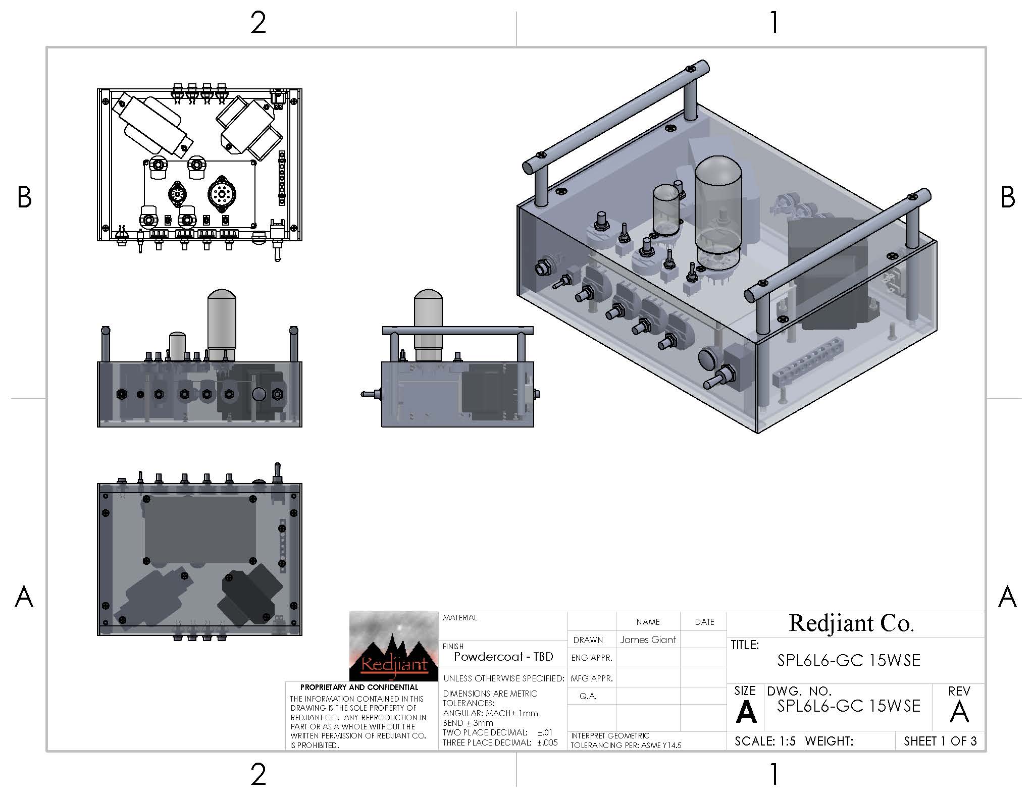
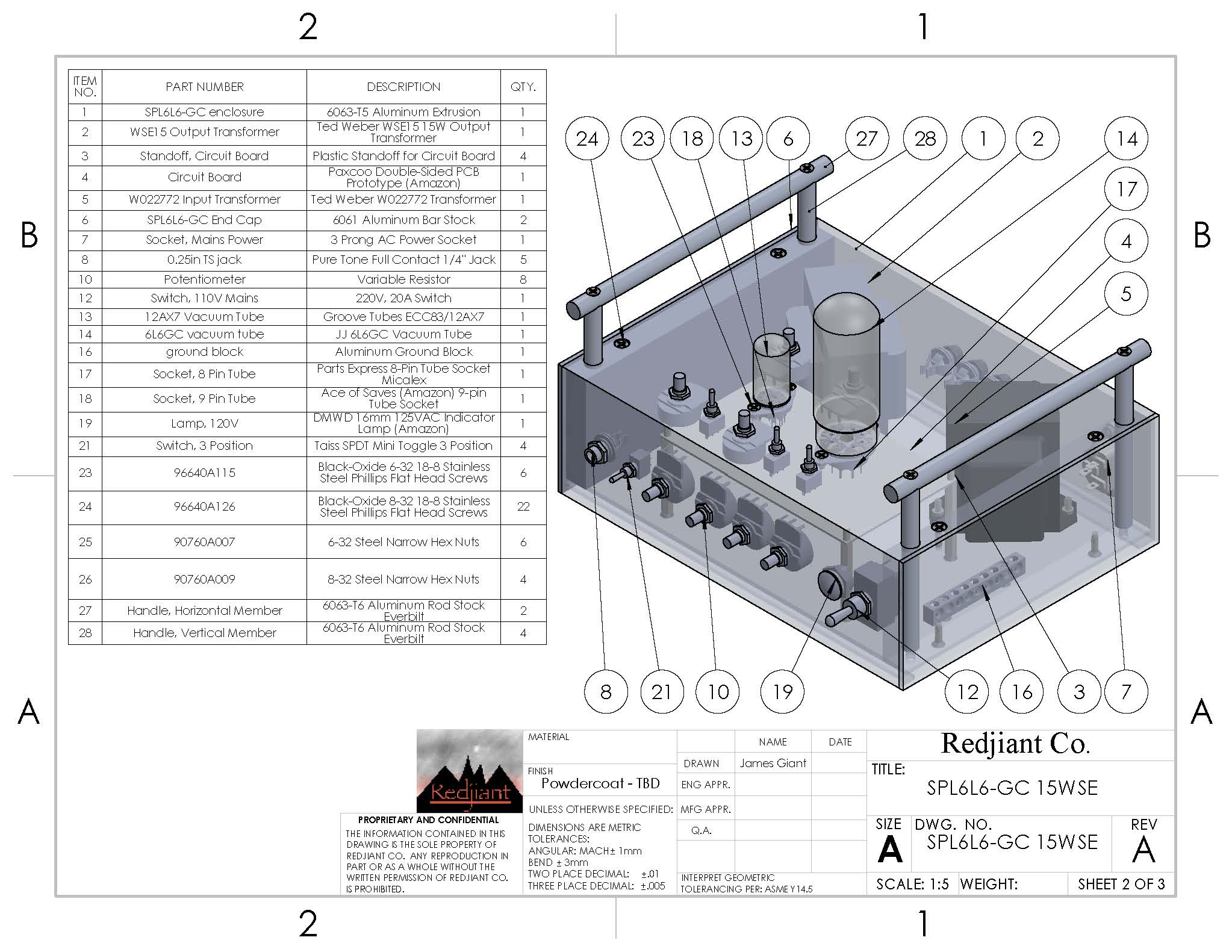
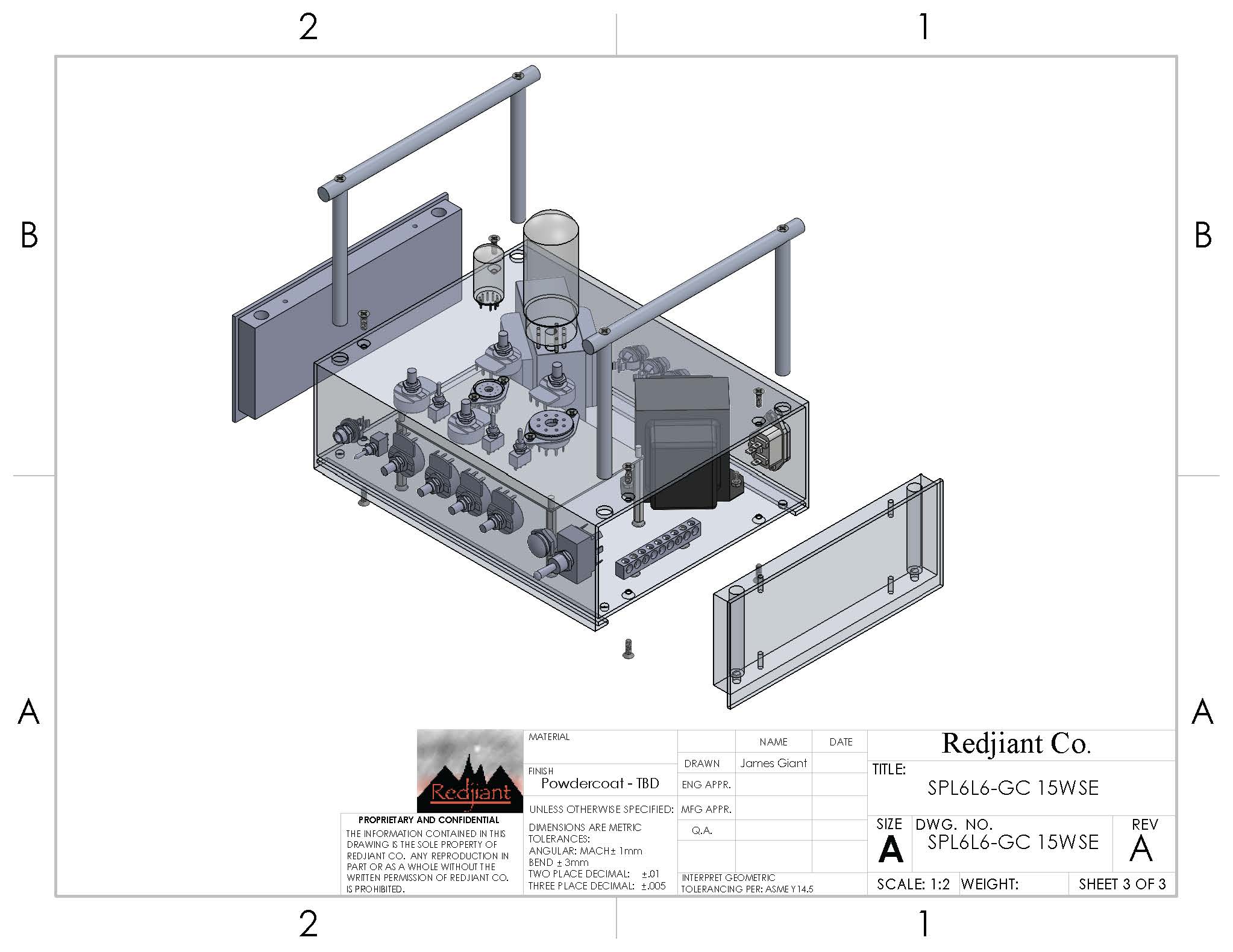
- Housed in a machined enclosure made of a 6063-T5 aluminum extrusion
What's Next?
- Fabricating the handle
- Powdercoating the enclosure
- Rebuilding prototype board and documenting the performance range on an oscilloscope
- labeling the potentiometer and switches
- Custom PCB
- El84 push-pull amplifier
- 8WSE el84 amp for fun